Machining Titanium: 5 Common Mistakes That Kill Your Tools
Ti-6Al-4V gives you roughly one-quarter to one-third the tool life of 304 stainless. Cutting speeds drop by half. Metal removal rates fall by more than 50%. Every shop supervisor who has run titanium knows these numbers.
But short tool life isn’t titanium’s fault. Most of the time it’s a process problem.
Our CNC shop machines more than five tonnes of titanium alloy parts every month. The five mistakes below are ones we’ve made ourselves and seen repeatedly on parts customers send back for rework. Each one comes with concrete parameters—not vague advice like “watch your cutting speed,” but numbers you can enter directly into the machine.
Mistake 1: Copying Stainless Steel Cutting Parameters
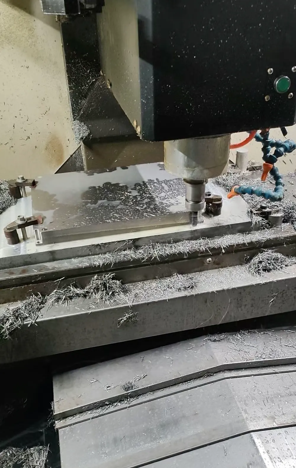
This is the most common mistake newcomers make, and the cause is straightforward.
The recommended cutting speed (Vc) for 304 stainless is 80–150 m/min. For Ti-6Al-4V it’s 40–60 m/min—half as fast. Yet many shops run their first titanium job with the same parameters they use for stainless, simply out of habit.
The result: tip temperature spikes past 600°C almost immediately. Titanium’s thermal conductivity is only about one-sixth that of steel, so heat concentrates at the cutting edge rather than dissipating through the workpiece. Carbide coatings burn off within three to five minutes. The insert is done. Worse, the high temperatures trigger surface hardening (alpha case) on the workpiece, making every subsequent operation even harder.
Corrective parameters:
- Vc: 40–60 m/min (use the lower end for finishing)
- Feed per tooth fz: 0.08–0.15 mm/tooth
- Axial depth ap: 2–4 mm roughing, 0.3–0.8 mm finishing
- Tooling: coated carbide (TiAlN or AlCrN), edge angle ≤45°
Mistake 2: Insufficient Coolant Flow or Wrong Nozzle Direction
Titanium machining depends on coolant far more than most other materials—this is not an exaggeration.
Stainless can be run with minimum quantity lubrication (MQL) or even dry. Titanium cannot. Because of titanium’s low thermal conductivity, if coolant does not precisely reach the cutting zone, local tip temperature can climb from 200°C to 800°C in seconds. The coating peels. The edge chips.
The typical failure is not “coolant turned off.” It’s insufficient flow, or a nozzle aimed at the chips rather than the tool-workpiece contact zone. Coolant hitting the side of the cut only cools the chips—it does nothing for the edge.
Corrective approach:
- Flow rate: ≥20 L/min (high-pressure coolant at 70–100 bar is optimal)
- Nozzle direction: aimed directly at the tool-workpiece contact zone, not at the chips
- Coolant concentration: 8–12% (higher than the 5–8% typical for stainless)
- Use through-spindle coolant if the machine supports it—tool life improves 30–50%
Mistake 3: Letting the Tool Dwell on the Workpiece
Titanium has an underappreciated characteristic: a low elastic modulus. Specifically, around 114 GPa—compared to 193 GPa for stainless steel and 69 GPa for aluminum. Titanium sits between the two.
This means titanium springs back under cutting pressure. When the tool pauses or decelerates at a position—direction reversals, program block transitions, any dwell—the workpiece rebounds against the cutting edge. The result is edge chipping or chatter marks on the machined surface.
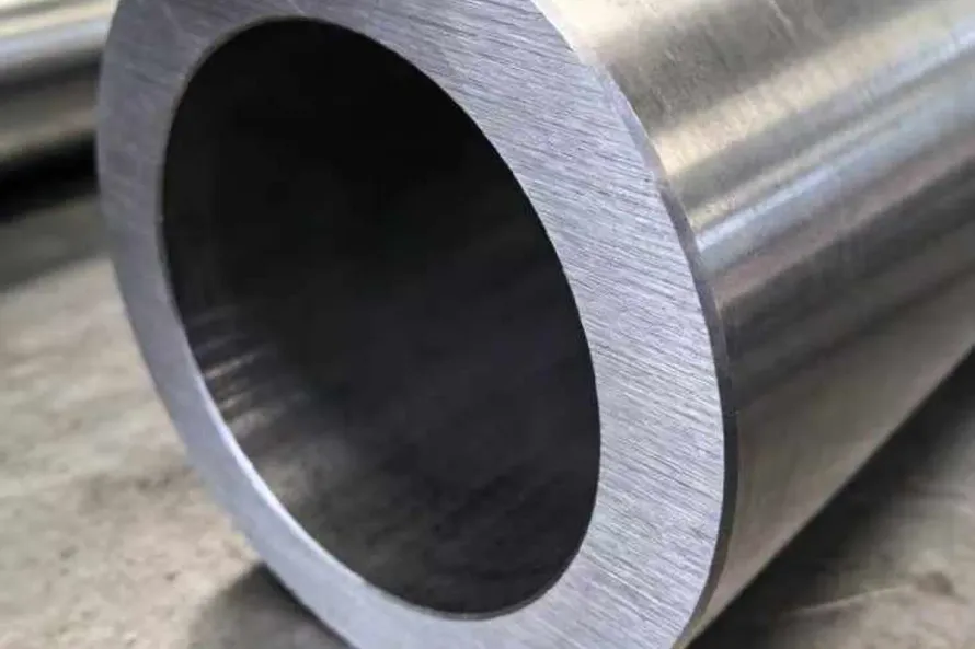
In our shop, this issue is most pronounced when machining thin-wall titanium tubes and titanium flanges. On parts with wall thickness below 3 mm, springback can reach 0.05–0.1 mm—enough to push dimensions out of tolerance.
Corrective approach:
- Program continuous feed throughout the cut—no dwell while the tool is engaged
- Use arc lead-in/lead-out on thin-wall parts; avoid straight plunge entry
- Use climb milling for finishing, not conventional milling—climb entry angles are shallower and springback is reduced
- Add auxiliary fixtures or supports to minimize thin-wall deflection
Mistake 4: Ignoring Chip Morphology
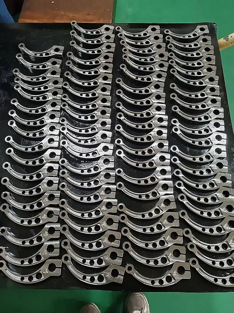
Chips tell you what’s happening at the cut. That’s not a figure of speech.
The ideal chip from titanium machining is a short, curled “C” or “6” shape. If you’re seeing long stringy ribbons wrapping around the tool, your parameters are off—usually feed is too low or depth of cut is too shallow.
Ribbon chips do more damage than just tangling. They re-enter the cut zone and generate secondary heat through friction, accelerating tool wear. The less obvious problem: ribbon chips score the finished surface, pushing surface roughness above spec. For precision machined parts requiring Ra ≤0.8, that’s a rejection criterion.
“We have a standing rule: if a chip exceeds 30 mm in length, stop and check the parameters. The right titanium chip is 5–15 mm long, curled, and breaking freely without wrapping the tool. When you see long chips, the first response isn’t more coolant—it’s more feed.” — Shop Supervisor Liu
Corrective approach:
- Keep feed per tooth at ≥0.06 mm/tooth—anything lower produces rubbing rather than cutting
- Use chip-breaker geometry inserts
- If chips remain long, try increasing depth of cut—deeper cuts produce thicker chips that break more readily
Mistake 5: Skipping Stress Relief After Machining
Titanium alloys work-harden more severely than most people expect.
During CNC machining, cutting forces and heat build residual stress in the workpiece surface layer. On simple geometries machined from bar stock, residual stress may not matter. But on thin-wall parts, complex structural components, or aerospace parts with strict fatigue life requirements, residual stress is a delayed failure mechanism.
A typical case we’ve seen: a batch of Ti-6Al-4V aerospace brackets passed all dimensional checks after machining, only to be returned by the customer after assembly—residual stress from machining released under thermal cycling and caused 0.1–0.2 mm warp across the part. The entire batch came back.
Corrective approach:
- Perform stress relief annealing after finish machining: 480–650°C, 1–4 hours, under vacuum or inert gas
- Add an intermediate anneal between roughing and finishing to release roughing stresses before the final pass—dimensional stability improves noticeably
- For parts with fatigue requirements (aerospace), AMS 2801 specifies the conditions under which stress relief is mandatory
All five mistakes are avoidable through parameter discipline. Titanium machining does not require special talent—it requires respect for the material’s properties. Our machining services team can provide full process recommendations based on your part drawings, from tooling selection through heat treatment. Send us your prints.
Related Products & Services
- Service → Titanium CNC Machining — Precision machining services for titanium alloys, from bar stock to finished parts
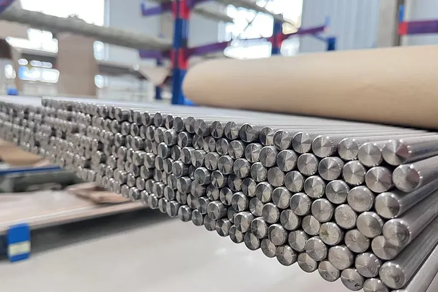
- Product → Titanium Rods — Gr.2/Gr.5 bar stock, the starting material for CNC machining
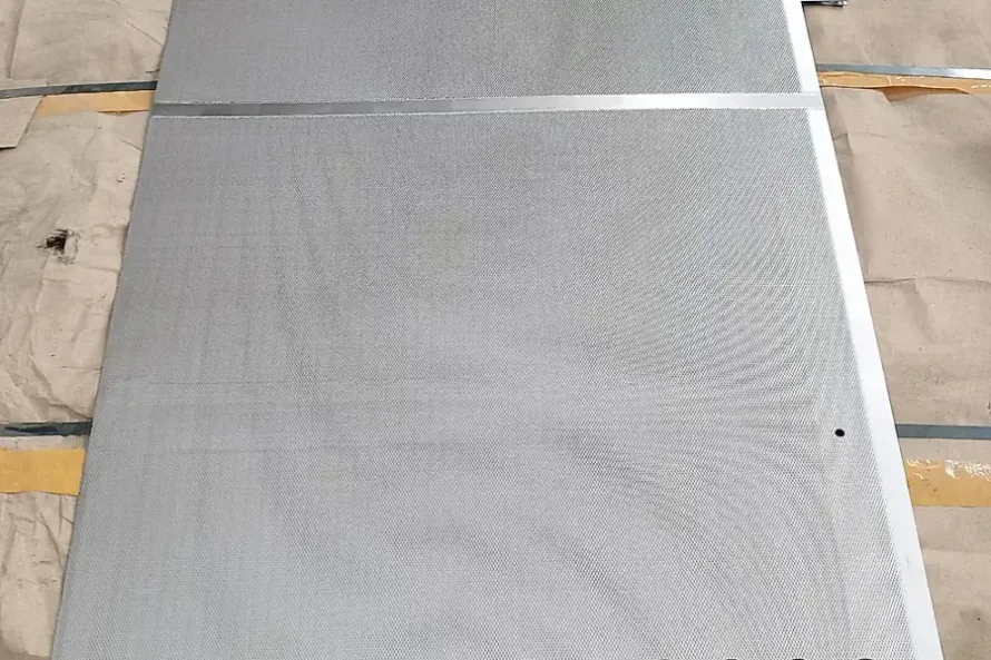
- Product → Titanium Sheets & Plates — Plate and sheet feedstock for machined components
Related Articles:
Need this material? Get a factory-direct quote.