New TC4 Study Turns Thin-Wall Milling Into a Moving-State Problem
A peer-reviewed study published by the Journal of Manufacturing and Materials Processing on 2026-09-01 validates a useful shift in how thin-wall titanium machining is modeled. The cutting condition is not fixed while the tool follows the programmed path. Material removal changes local stiffness, elastic deflection changes engagement, and flank wear changes force (Journal of Manufacturing and Materials Processing).
The study does not provide a universal compensation table. Its practical value is the coupling: a tolerance claim for a flexible titanium part should remain attached to the workpiece state, removal sequence, tool condition and verification method that produced it.
The cutting condition moves with the part
Conventional process documentation can make a milling operation look static: speed, feed, depth, tool and fixture are listed once. A thin wall changes that picture. Each pass removes material and reduces stiffness. The resulting deflection changes actual chip thickness, depth of cut and tool-workpiece engagement, which feeds back into cutting force.
The researchers represented that loop with an iterative method. A mechanistic cutting-force model incorporated flank-wear width. The workpiece stiffness matrix was updated at successive feed positions as material was removed. Predicted deformation then changed the effective cutting state used in the next force calculation.
One sensitivity case shows why the update matters. At a removal height of 40 mm and removed thickness of 2 mm, neglecting material removal produced a maximum relative deformation difference of 20.4%. This is not a general error rate for all thin walls. It demonstrates that a model can lose the state of the part if it carries the original stiffness through a later machining layer.
Wear and deflection pull in different directions
Tool wear generally raises cutting force. Workpiece deflection can reduce actual engagement and therefore reduce the force predicted from nominal geometry. In the study’s analyzed cases, adding flexibility reduced predicted peak values of Fy and Fz by as much as 6.4% and 4.3%, while increased wear raised them by as much as 20% and 3.6%.
Those effects should not be combined into a casual rule that they cancel. Their magnitudes vary by direction, location, wear state and remaining geometry. The important mechanism is that two evolving variables act through different paths. A wear-only correction can misstate force if it ignores deflection; in the analyzed cases, neglecting flexibility overstated peak force. A stiffness-only correction can miss the loading growth caused by the tool.
For production, that makes a tool change more than a consumables event and a layer transition more than a program coordinate. Both can change the evidence needed to support dimensional capability.
Validation is specific, not universal
The authors tested a TC4 thin-wall workpiece measuring 94 mm x 52 mm x 5 mm. They measured cutting force, inspected flank wear and used a coordinate measuring machine to measure force-induced deformation.
For the flexible-workpiece force comparison, average peak-value errors for Fy and Fz were 7.8% and 5.5% with a new tool and 5.9% and 6.1% with flank-wear width VB = 0.05 mm. Average deformation prediction errors were 11.8% for the new-tool condition and 14.5% for the VB = 0.05 mm condition. The model also reproduced the reported U-shaped spatial trend: lower deformation in the stiffer middle region and higher deformation near less constrained ends.
These results support the method inside the tested envelope. They do not prove that the same errors apply to another wall thickness, fixture, cutter, machine, alloy route or residual-stress state. In the validation, flank wear was prescribed by machining layer rather than continuously evolved along the path. Bottom-edge cutting, uneven tooth wear and dynamic tool-workpiece displacement were not explicitly represented.
A five-state machining envelope for buyers
Buyers of thin-wall titanium components can turn the study into a compact evidence request:
| State | Buyer question | Evidence to retain |
|---|---|---|
| Incoming blank | What alloy, product route, initial geometry and residual condition entered machining? | Material identity and pre-machining inspection |
| Support and stiffness | Which fixture, overhang and local wall geometry defined compliance? | Setup record and geometry-linked stiffness or prove-out evidence |
| Removal sequence | How did each pass change wall thickness and load position? | Toolpath, layer order and intermediate-state definition |
| Tool condition | How was flank wear measured, limited or reset? | Wear criterion, inspection frequency and tool-change record |
| Measured endpoint | Which dimensions and surface conditions prove acceptance after unclamping? | CMM or equivalent final inspection tied to the released part |
The framework separates a supplier’s ability to run a machine from its ability to hold a specific thin-wall feature. A generic titanium CNC machining capability statement is useful background, but a critical tolerance needs geometry- and state-specific evidence. Likewise, starting from controlled titanium sheet and plate does not remove the need to track how the wall changes during finishing.
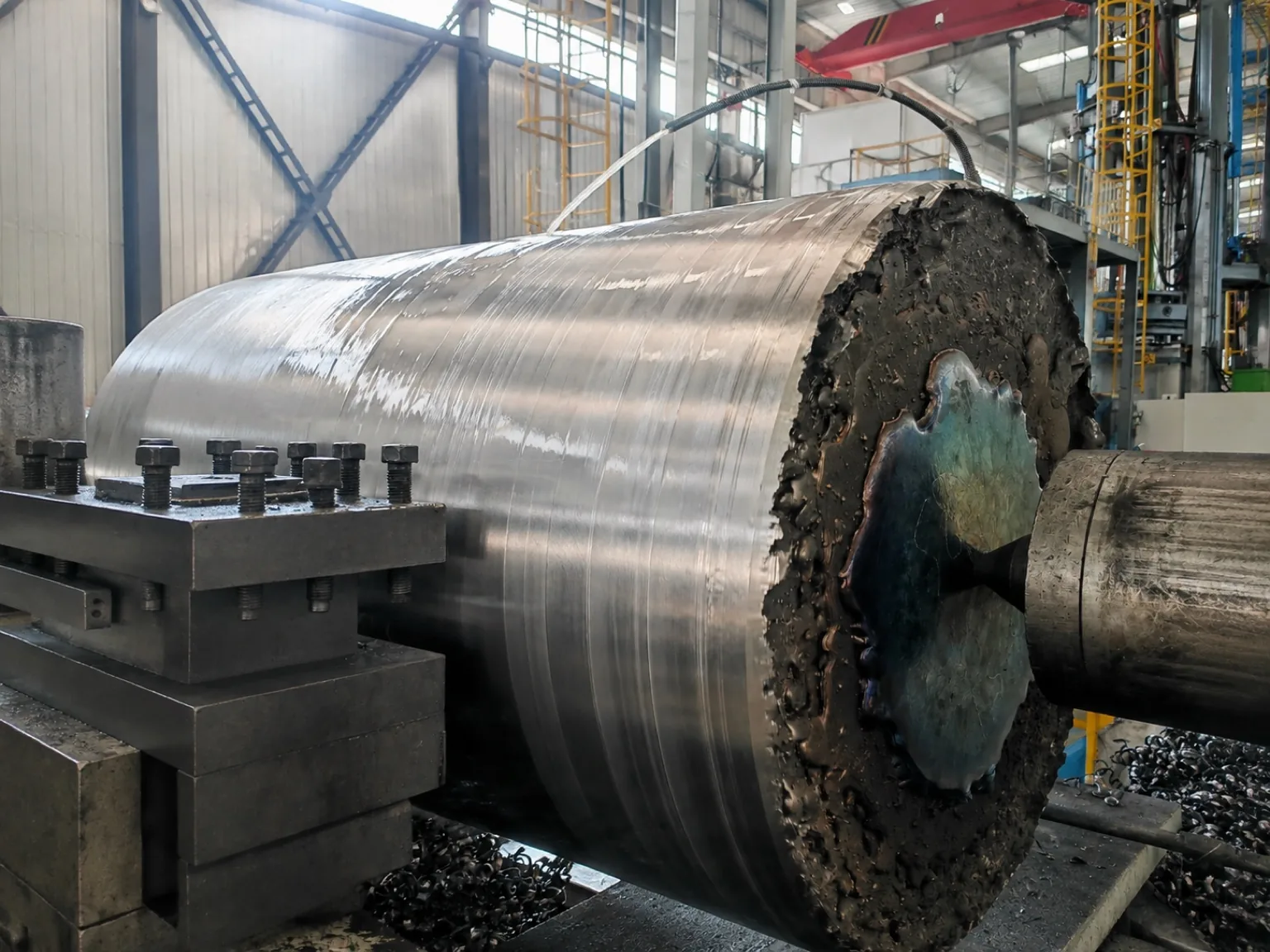
What changes in an RFQ
An RFQ that asks only for final thickness and profile leaves the process risk hidden. For a flexible feature, the buyer should also identify the datum condition, inspection state, unclamped measurement requirement, critical removal sequence and any tool-wear checkpoint that supports the tolerance.
The supplier does not need to use this paper’s exact model. A validated finite-element method, compensation strategy, staged inspection plan or conservative process limit may serve the same commercial purpose. What matters is that the evidence follows the moving state of the part rather than assuming the first pass and last pass are mechanically equivalent.
The study’s durable conclusion is therefore about control architecture. Thin-wall milling is a coupled path, not a static recipe. A credible release file should show how remaining stiffness, tool condition and measured deformation were kept connected from blank to finished component.
Source boundary: This analysis uses the complete publisher PDF for DOI 10.3390/jmmp10090326. Reported errors and percentage effects are confined to the paper’s test and simulation conditions and are not presented as universal machining capability values.
FAQ
# What does the new TC4 thin-wall milling model couple?
# What was the largest reported material-removal sensitivity?
# Are the reported prediction errors universal machining tolerances?
# What evidence should a thin-wall titanium buyer request?
Need this material? Get a factory-direct quote.